A novice electronic test engineer needs to understand 8 SMT testing techniques
Oct 20, 2021
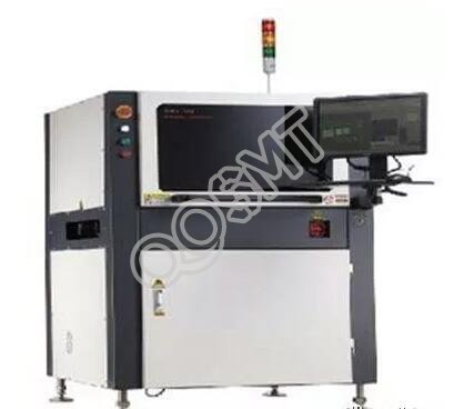
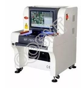
1. SPI solder paste detector
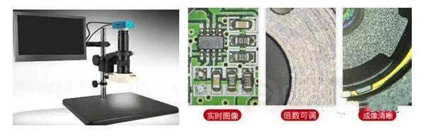
3, digital microscope
8, FCT functional test (Functional Tester)
With the miniaturization of electronic products, the development of high-density assembly of components on circuit boards has brought great challenges to SMT production and testing. From the detection method, it can be subdivided into: manual visual inspection, digital microscope, SPI solder paste detector, automatic optical inspection (AOI), SMT first piece detector, online test (referred to as ICT minute needle bed, flying needle), functional inspection ( FCT), automatic X-ray inspection (X-ray or AXI for short) and other methods, here is a brief introduction to the main SMT inspection techniques above.
1. SPI solder paste detector
The SPI solder paste detector uses the principle of optics to calculate the height of the solder paste printed on the PCB through the method of triangulation. Its function is to detect and analyze the quality of the solder paste printing, and find SMT process defects in advance, so that you can use it. The operator monitors the problems in the production in real time, reduces the defects caused by poor solder paste printing, provides strong quality control support to the operators, and enhances the process performance.
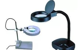
2. Manual visual inspection
Manual visual inspection is the use of human eyes with the aid of a magnifying glass with or without illumination to inspect the appearance of printed circuit boards and solder joints, missing parts, wrong parts, reverse polarity, offset, and tombstone quality problems.
3, digital microscope
The digital microscope converts the physical image seen by the microscope through digital-to-analog conversion. It magnifies the physical image and displays it on the computer screen. The picture can be saved, enlarged, and printed. With measurement software, various data can be measured. It is suitable for the inspection of electronic industry production lines, the inspection of printed circuit boards, and the inspection of soldering defects in printed circuit components.
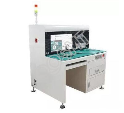
4, the first SMT tester
Through intelligent integration of CAD coordinates, BOM list and the first PCB scan, the system automatically enters the measurement data, so that the first inspection of the SMT production line can be simplified. The LCR reads the data and automatically corresponds to the corresponding position and automatically judges the inspection result. Eliminate false tests and missed tests, and automatically generate test reports and store them in the database. Test reports are stored in the database.
5, AOI automatic optical inspection
AOI (Automated Optical Inspection) is a new type of technology that uses optical and digital imaging technology, and uses computer and software technology to analyze images for automatic inspection.
AOI equipment can generally be divided into two categories: online (in the production line) and offline.
AOI inspection is a kind of inspection technology formed by the integration of computer technology, high-speed image processing and recognition technology, automatic control technology, precision mechanical technology and optical technology.
AOI automatically scans the PCB through the camera, collects images, compares the tested solder joints with the qualified parameters in the database, and after image processing, checks out the defects on the PCB: missing parts, wrong parts, bad parts, solder balls, offset, side Stand, tombstone, reverse paste, extreme reverse, bridge, virtual solder, no solder, less solder, more solder, component floating, IC pin floating, IC pin bending, and display defects through the display or automatic signs / Mark it out for repair by maintenance personnel.
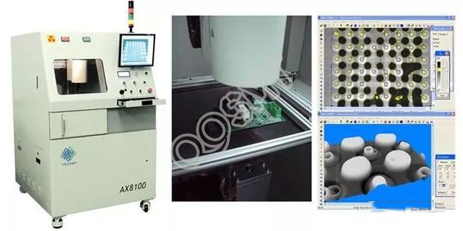
6 X-ray inspection (referred to as X-ray or AXI)
Automatic X-ray inspection AXI (AutomaticX-raylnspection)
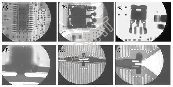
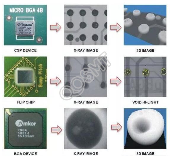
X-Ray inspection uses X-ray penetrating material and attenuation in the material to find defects. It mainly detects internal defects of solder joints, such as the solder joint detection of BGA, CSP and Chip in FC.
X-ray inspection is to use X-rays with strong penetrability and ability to penetrate the surface of the object to see through the inside of the solder joints to be inspected, so as to detect and analyze the welding quality of various common solder joints of electronic components.
X-Ray inspection can fully reflect the welding quality of solder joints, including open circuits, short circuits, holes, holes, internal bubbles, and insufficient tin, and can perform quantitative analysis. The biggest feature of X-ray inspection is that it can detect solder joint defects under BGA packaged devices, such as bridges, open circuits, missing solder balls, displacement, insufficient solder, cavities, solder balls, and fuzzy edges of solder joints.
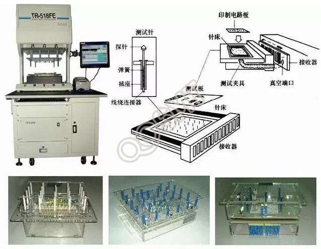
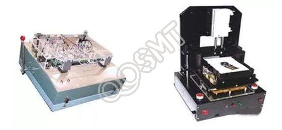
7, ICT online tester
ICT online tester, ICT, In-Circuit Test, is a standard test method to check the manufacturing defects and defective components by testing the electrical performance and electrical connection of online components. Use a special needle bed to contact the solder joints of the components on the soldered circuit board, and use a voltage of hundreds of millivolts and a current of less than 10 milliamps to conduct a discrete isolation test, thereby accurately measuring the installed resistance, inductance, capacitance, and Common and special components such as diodes, thyristors, field effect tubes, integrated blocks, etc. are missing, wrongly installed, parameter value deviation, solder joint welding, circuit board open and short circuit and other faults.
ICT is divided into flying probe ICT and needle bed type ICT: Needle bed type ICT can carry out analog device function and digital device logic function test, and the fault coverage rate is high. However, special needle bed fixtures, fixture production and procedures are required for each type of veneer. Long development cycle.
The flying probe tester is an improvement of the traditional needle bed online tester. It uses probes to replace the needle bed. The x-y mechanism is equipped with 4 to 8 test probes (flying probes) that can move at a high speed. , The minimum test gap is 0.2mm. The flying probe ICT basically only performs static testing. The advantage is that it does not need to make fixtures and the program development time is short, but the relatively slow test speed is its biggest disadvantage.
8, FCT functional test (Functional Tester)
Functional Test (FCT: Functional Circuit Test) refers to a test method that provides a simulated operating environment for the test circuit board, makes the circuit board work in the design state, and obtains output to verify the functional state of the circuit board. Simply put, it is to connect the dedicated circuit board on an assembled electronic device to the appropriate circuit of the device, and then apply voltage. If the device works normally, the circuit board is qualified.
The above 8 detailed descriptions of the combined test method used in the test of highly complex circuit boards, and which method is used should be determined according to the specific conditions of the SMT production line and the assembly density of the surface mount components.