Why does the product not turn on after SMT? Something to do with the Kirkendall Hollow?
Jan 12, 2024
A certain product fails to boot after SMT. After preliminary investigation, it was suspected that the DDR solder joints were poorly welded, causing the computer to fail to boot. After testing and analysis, it was found that there was a Kirkendall void.
test analysis
1. Appearance inspection
Visual inspection using a stereomicroscope revealed that the corner solder joints of the failed BGA were well formed, the solder pads were well wetted, and the solder joint surfaces were bright. No obvious bridging, false soldering, pillow soldering, or other abnormalities were found.
2. X-Ray&CT tomography analysis
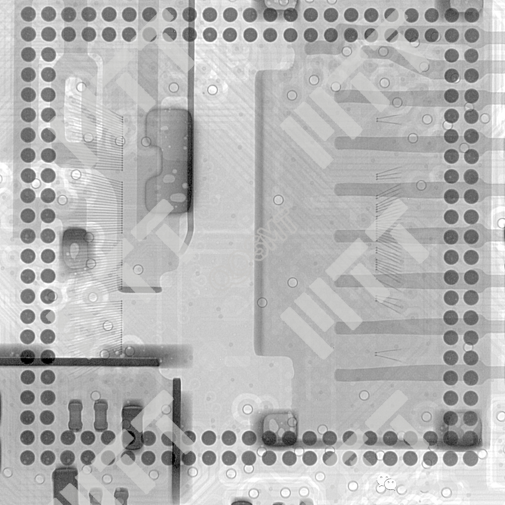
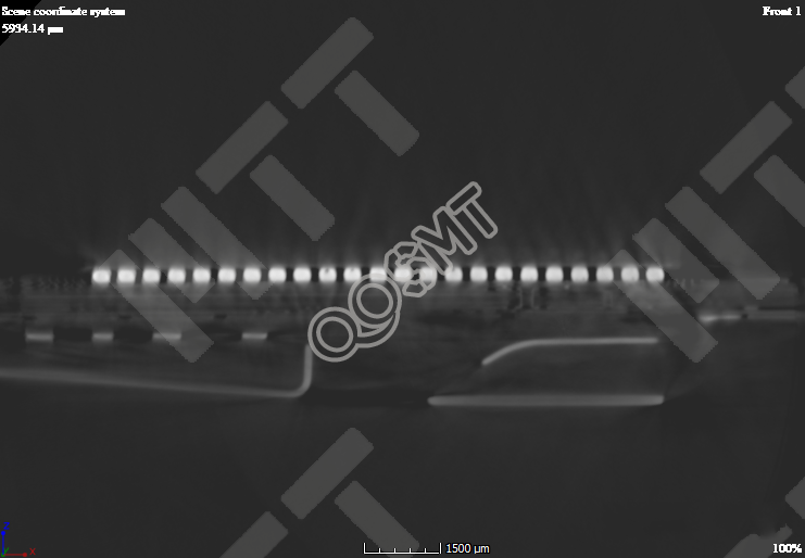
Observation through X-Ray & CT non-destructive fluoroscopy technology showed that the X-Ray and CT scan results showed that the solder joints were well formed, and no abnormalities such as obvious bridges, empty solder joints, and pillow-shaped solder joints were found.
Figure 1. X-Ray scan results
Figure 2. CT scan results
3. Red ink staining test & section analysis
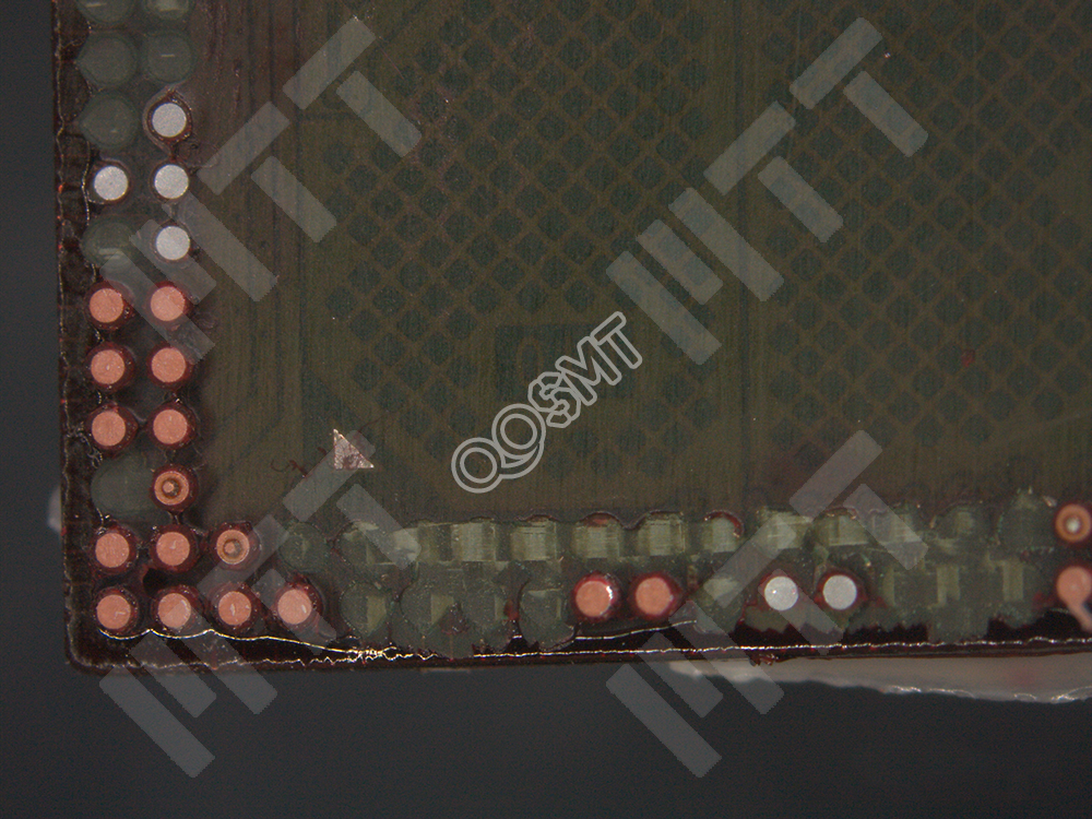
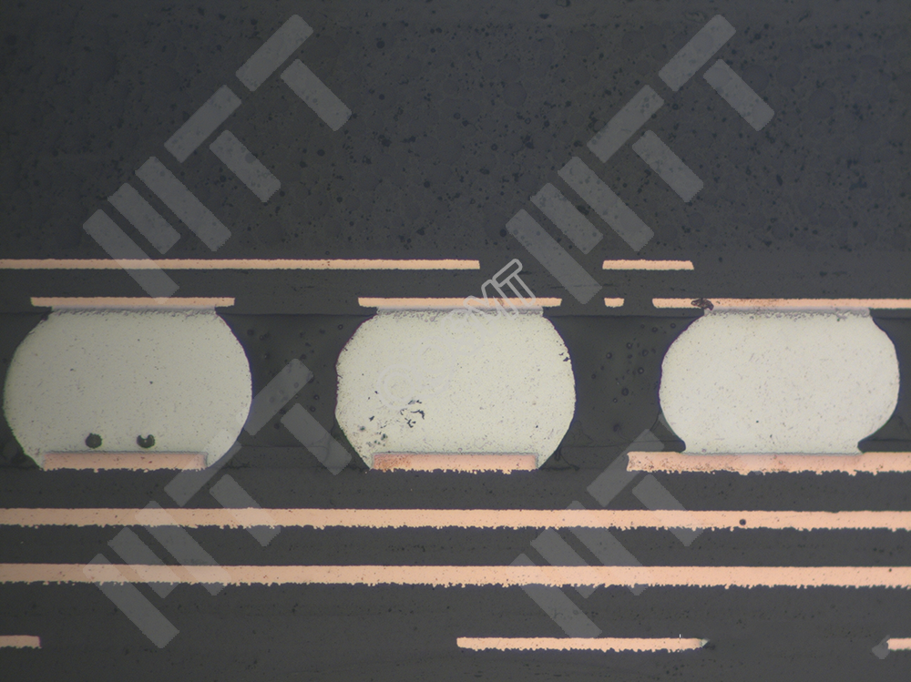
The welding quality of the solder joints was inspected through the red ink dyeing test and slicing method; no obvious staining was observed in the red ink dyeing test results, and the slicing results showed that the solder joints were completely welded.
OK, no obvious welding abnormalities were found.
Figure 3. Red ink staining results
Figure 4. Slicing results
4. Chip analysis
Through the above tests, no abnormal welding phenomena were found, which can rule out the impact of poor welding on product failure. The following uses ultrasonic scanning, chemical unsealing, ion cutting and SEM observation techniques.
Technology to analyze chip packaging and bonding quality.
4.1 Ultrasonic scan analysis
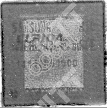
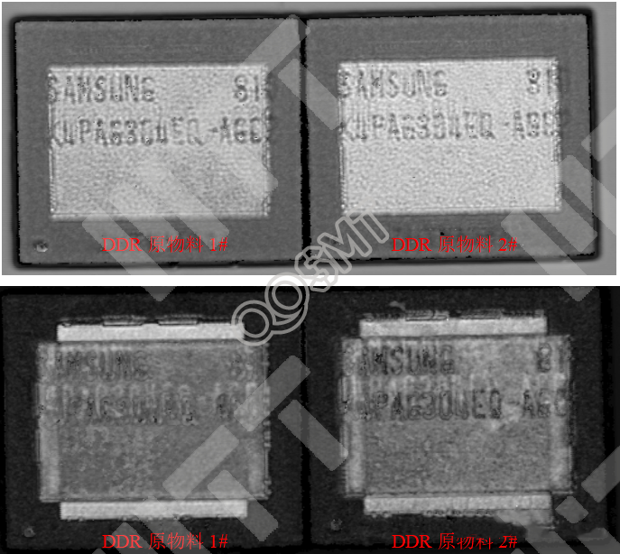
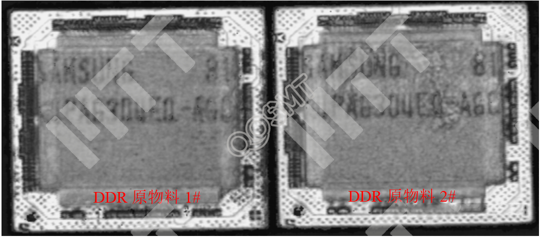
Use an ultrasonic scanning microscope to test failed products and DDR raw materials in order to observe whether there are delamination abnormalities inside the chip. The results are shown in Figure 5-10.
Ultrasonic results showed that no obvious delamination abnormalities were found inside the failed products and DDR raw materials.
(Note: The red image represents delamination abnormality. The image result does not show the red warning color, indicating that there is no delamination abnormality inside the package)
Figure 5. Failure product-1
Die surface image
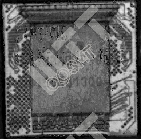
Figure 6. Failure product-1
Substrate surface image
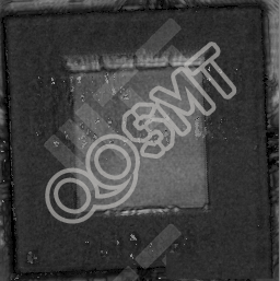
Figure 7. Failure product-2
Die surface image
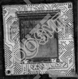
Figure 8. Failure product-2
Substrate surface image
Figure 9. DDR raw material Die surface image
Figure 10. DDR original Substrate surface image
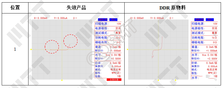
4.2 IV characteristic curve measurement
In order to confirm whether the electrical properties of the failed product are abnormal, a transistor grapher was used to measure the IV characteristic curves of important pins; the results are shown in Figure 11. The failed product was in some cases better than the DDR raw materials.
On the pin, there are some differences in the IV characteristic curve.
Figure 11. Measurement results of IV characteristic curves of failed products and DDR raw materials
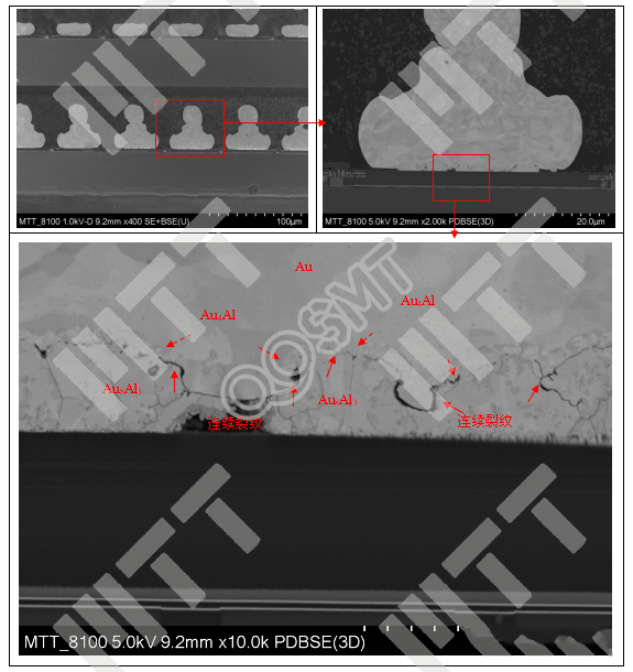
4.3 Analysis of bonding point welding quality
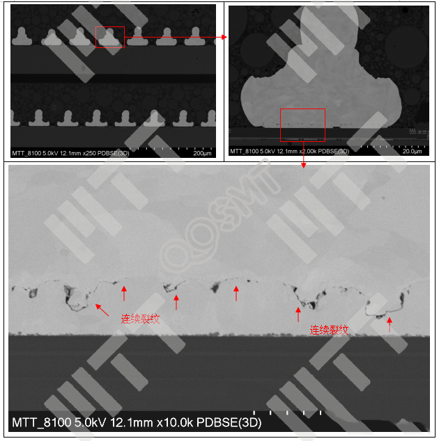
The inspection results found that there were obviously many continuous cracks at the bonding point, and the crack location was the gold-aluminum alloy welding interface. This failure phenomenon is called Kirkendall void failure.
Figure 12. SEM observation results of failed product after CP treatment
Figure 13. SEM observation results of DDR raw materials after CP treatment
5. Failure mechanism
5.1 Kirkendall void
In the wire bonding process, Au-Al IMC (Inter-Metallic Compounds) will be formed between the pure gold wire and the aluminum pad. Different stages of gold and aluminum eutectics will form
into different compounds. Usually gold and aluminum first form Au8Al3 compounds. As bonding continues, Au8Al3 will continue to eutectic to form Au2Al. At this time, the compounds on the IMC interface
How the eutectic proceeds will be determined by the ratio of gold and aluminum at the bond site.
In a high temperature environment, the original IMC will continue to grow into compounds such as Au8Al3, Au2Al, AuAl2, AuAl, Au4Al after completing the bonding process. The materials of these IMCs are particularly
Properties vary, and compared with gold and aluminum, the thermal expansion coefficient of gold-aluminum IMC is quite low. There are many grain boundaries between different compounds inside IMC, and there are many lattice defects such as stress and impurity.
Moreover, these IMCs are harder and more brittle than gold and aluminum. In high-temperature environments, the growth rate of IMCs will be accelerated, forming Kirkendall voids, which are prone to cracks and open circuits. Therefore, high temperature storage
Testing is used as a common method to detect potential bond failures.
5.2 Failure mechanism
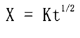
Kirkendall voids are caused by the growth of IMC, and the growth of IMC basically follows a parabolic relationship.
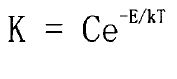
Where X - IMC thickness (um), K - diffusivity constant, t - aging time (sec). The calculation formula for diffusion coefficient is as follows:
Among them, C is the constant, E is the activation energy, k is the Boltzmann constant, and T is the absolute temperature.
For 99.99% high-purity gold wire K=1.9X10⁻¹²cm2/sec, through the above formula we can see that the IMC thickness will inevitably grow with the increase of high temperature aging time
, and ultimately cause Kirkendall void failure due to lattice defects. Therefore, how to effectively delay and avoid the excessive growth of IMC is crucial to ensuring product reliability.
One detail we can observe is that the thickness of IMC is only related to two variables: time and temperature. Time cannot be controlled, but temperature can, so the reduction
Low temperature can slow down the growth rate of IMC, thereby extending the service life of the device.
6 Conclusion
The root cause of the product not booting is that the chip body is defective and there is a Kirkendall void phenomenon, which causes the product to not boot.