CPK measurement of Panasonic CM402DT401-F
Jan 20, 2024
11. Correct mount position 2
1. Preparation:
1. For the CM402 high-speed head, you need: glass substrate 240×215, 1005 material, 110 nozzle, special lamp and its power supply or dry battery, double-sided tape
2. For the CM402 general-purpose head, you need: glass substrate 240×215, test fixture (QFP as material sample), 1003, 1004, 1005 nozzles, special lamp and its power supply or dry battery, double-sided tape
3. For DT401-F, you need: glass substrate 240×215, test fixture (QFP as material sample), tray fixture, tray, 3 nozzles for 1003 and 1005, special lamp and its power supply or dry battery, Double sided tape
2. Preliminary work (taking DT401 as an example)
1. Use double-sided tape to glue the glass substrate;
2. Copy the appropriate program into the machine through a floppy disk (usually 45 degrees) and return the machine to the original position;
3. Install the jig table and the jig on the pallet;
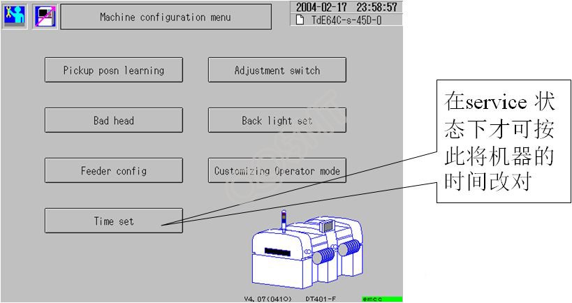
4. Modify the machine time, see the next page;
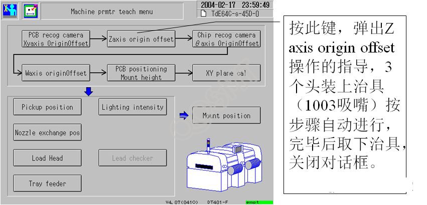
5. Perform Z-axis origin correction;
3. Modify the machine time
4. Z-axis origin correction
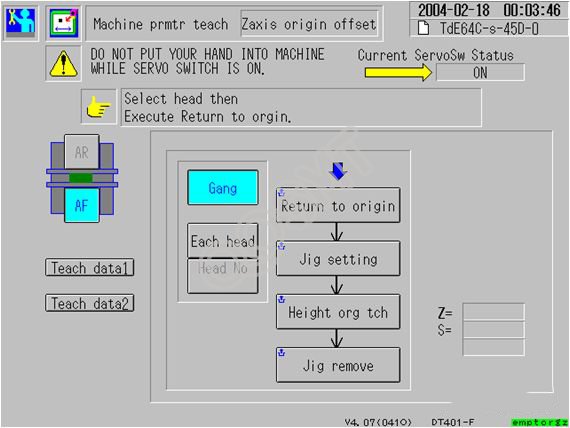
5. Detailed operation diagram of Z-axis origin correction
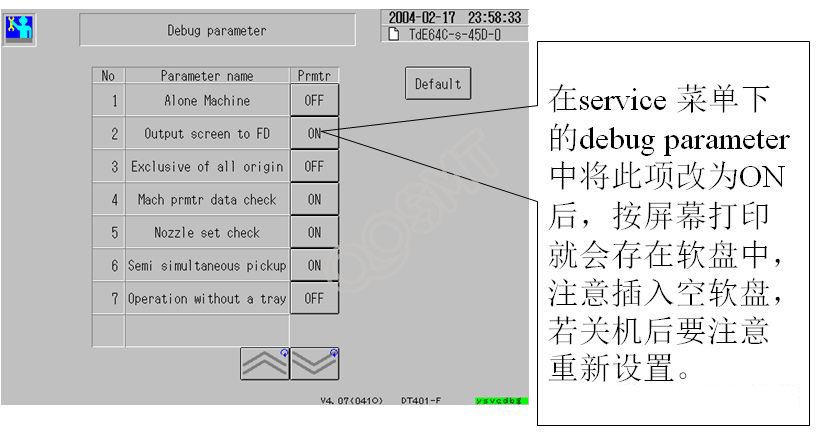
6. Set up screen printing to floppy disk
7. Preparation for starting measurement
1. Place the glass fixture QFP on the bracket. Pay attention to only place 4 to 18 stations. At the same time, the bracket should be aligned with the standard feeder number;
2. In tray No.1, the glass fixtures QFP are also installed with jigs, 3 in the X direction and 5 in the Y direction; ª A total of 30 glass fixtures are used in the above to QFP (need to be cleaned), and the directions of QFP are all for human installation. The missing corner of the material is in the upper left corner;
3. Place the lighting in a suitable position and turn it on. Note that improper placement may affect the identification of the fixture;
8. Measurement
1. Select the placement position measurement in the production screen. The machine will perform placement at a slower speed and the placement will be measured;
2. After the above is completed, perform the accuracy measurement with the same preparation. At this time, the machine's placement speed will be faster. After completion, the accuracy measurement is performed.
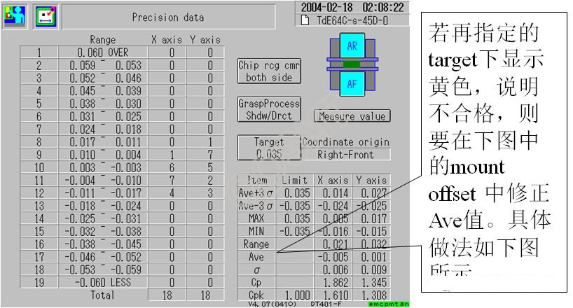
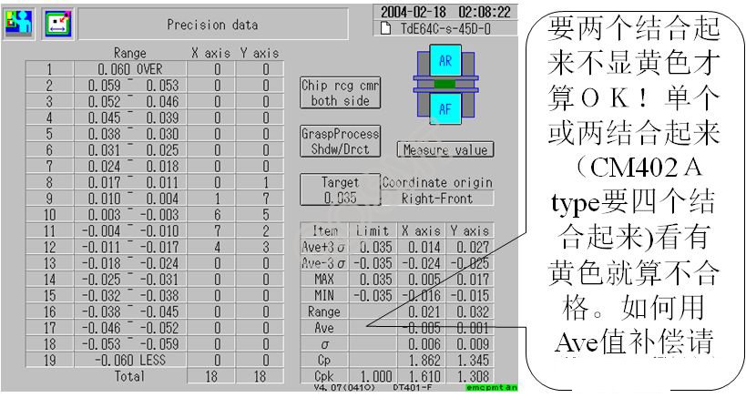
3. After completing the above, enter the machine parameter as shown in the figure below. The index of high-speed machines is 0.050, and the index of general-purpose machines is 0.035. If it shows yellow, it means it is not possible. to be corrected
9. Precision data analysis
10. Correct mount position1
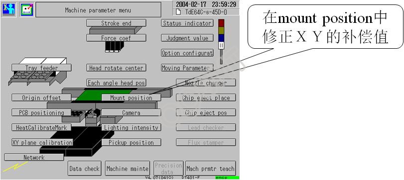
11. Correct mount position 2
12. Compensate the Ave value into the mount position