Detailed introduction to the feeding system (feeder) of SMT placement machine
Jan 22, 2024
Preface
Feeder, also known as feeder or feeder, the feeding system composed of the feeder, its load-bearing installation mechanism and detection mechanism is one of the three basic systems of the placement machine, which has a great influence on the function and performance of the placement machine. .
1. Overview of feeder
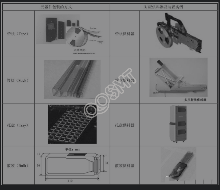
1. Feeder and component packaging methods
Feeder, also known as feeder or feeder (transliteration of Feeder), is an important component in placement technology that affects placement capacity and production efficiency. It is also the most important accessory of the placement machine, so that some placement machines The number of feeders that can be accommodated is directly used as a mark in the machine model. Different types of surface mount components use different packaging, and different packaging requires corresponding feeders. In the placement machine, the components are supplied to the nozzle through the feeder according to the instructions of the placement machine. Therefore, the packaging form and quality of the feeder and surface mount components are important to the pick-up component process. effect.
The following table is an example of component packaging methods and corresponding feeders.
Note: A surface mount component can be packaged in different packages. For example, chip resistors are mostly packaged in tapes and are also available in bulk; QFP packaged integrated circuits are packaged in both tubes and trays.
2. Feeder and placement machine
Different types of placement machines have different support for feeders. The overhead arch type machine can support different feeder types, including Bulk, Tape-and-Real, Tube, Odd-Form and other design types. In contrast, high-speed turrets and massively parallel systems are fed entirely from bulk bins or tape packages.
When components are packaged in a format other than bulk or strip form, an overhead rack machine may be the only option. High-speed machines were excluded from consideration because they cannot feed these materials automatically.
From a logical perspective, manufacturers should look for chip equipment that can expand their existing chip components. For example, some manufacturers' equipment may require feeders designed specifically for a specific machine, limiting the use of the feeders. This feeder limit requires the use of resources to track and record which feeders can handle which components. Because there are machine-specific feeders, storage of replacement or unused feeders can take up a lot of floor space. In an age where operations are measured by metrics, such as throughput per unit of floor space, potential manufacturing space used to house component patching or surrounding equipment for other substrate-critical functions can be considered waste. This is why module systems are gaining popularity. When components like feeders can be used on similar machines, a more efficient approach to component placement and manufacturing is enhanced.
Nonetheless, it is beneficial to fully examine and understand the number and types of components that may be used in a given PCB design. As electronics manufacturers turn to module assembly lines, it's important to remember that traditional configurations—high-speed placement machines plus fine-pitch placement machines—are also an option for some high-die-volume applications, such as cellular phones and computers. motherboard.
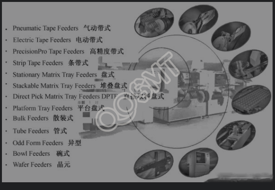
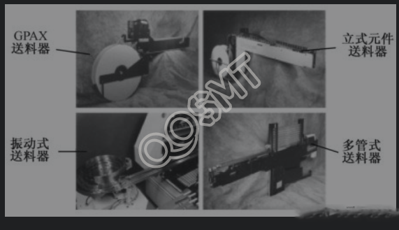
Common feeder types are shown in the figure below.
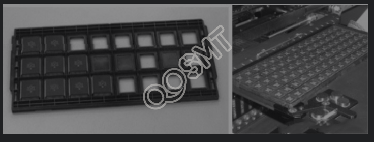
2. Tray feeder
The tray feeder (as shown in the figure below) has single-layer and multi-layer structures. The single-layer tray feeder is directly installed on the feeder frame and occupies multiple slots. It is suitable for situations where there is not much tray material; The multi-layer tray feeder has multiple layers of automatic transmission trays and a compact structure. It is suitable for situations where there are a lot of tray materials. Most of the tray components are various IC integrated circuit components. It can save space on the feeder rack, such as Universal's PTF (Platform Tray Feeder) and DPTF (Direct Platform Tray Feeder).
When loading the matrix plate, attention should be paid to protecting the exposed components of the large tube corners to prevent damage to mechanical and electrical properties during transportation and use. When using TSOP, PQFP, TQFP, BGA and SSOPs components in the pallet, the pallet size can reach 150mm x 330.2mm (6 in x 13 in) and 25.4mm (1 in) high. The pallet can also be used as a disposal station for valuable components. All pallets are standard sizes and comply with standard JEDEC requirements. The tray material is carbon-filled and has an electrostatic coating to provide ESD protection. Some trays can be used continuously at 150°C for multiple times and can be processed in an oven.
There is also a type called waffle packaging, which is used for bare chips and small components. It can be called a small tray. The tray material is usually a conductive material and is 2 in × 2 in in size. Place all the bare chips in the zigzag opening, and ensure the consistency of the direction; the number of bare chips determines the number of teeth in the opening, dust-free paper is placed under the bare chips, and plastic clips can be used to uniformly seal the 5 packages together.
(1) PTF - high-power, fast and flexible matrix tray feeder
Platform tray feeder PTF, as shown in the figure below.
• Productivity can be increased through group retrieval of components;
• Up to 58 different components can be used in the matrix tray;
• The integral structure does not need to occupy the feeder station;
• Components and pallets are defined from the host;
• Standard pre-rotatable head;
• Pallets are removed automatically.
(2) DPIF - a matrix tray feeder with moderate capabilities, high speed and flexibility
Directly pick up the tray feeder DPTF as shown in the figure below.
• Lightweight structure;
• Take material directly from the head;
• The material box can be replaced;
• Up to 28 components available;
• Support vacuum blister;
• Connected to the machine and occupy one feeder frame position (18 slots);
• Components and pallets are defined from the host.
(3) Other tray feeders
The stackable tray feeder STF and the fixed matrix tray feeder STF are shown in Figure 1 and Figure 2 below.
Figure 1 Stackable tray feeder STF
Disk width is 6.1 in or 8.3 in
Fixed matrix tray feeder STF
Disc widths are 6.1 in, 9.75 in and 13 in
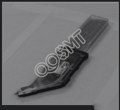
3. Belt feeder
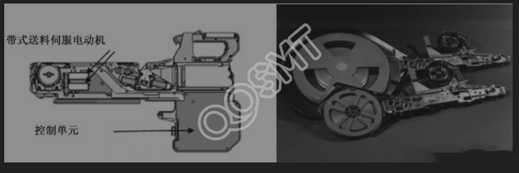
Belt feeder is the most commonly used standard feeder. The traditional structural methods include wheel, claw, pneumatic and multi-spacing electric. It has now developed into a high-precision electric type. Compared with traditional methods, it has faster feeding speed and higher transmission accuracy. , the structure is more compact, the performance is stable, and the production efficiency is greatly improved. The figure below shows the structure and example of a belt feeder.
The feeder has 3 components: feeder, reel and tape, with different widths and spacing depending on the size of the component.
(1) Basic specifications of strip materials
• Basic width: 8mm, 12mm, 16mm, 24mm, 32mm, 44mm and 52mm and other types;
• Strip spacing (center to center of adjacent components): 2mm, 4mm, 8mm, 12mm and 16mm;
• There are two types of ribbon materials: paper and plastic;
• The height of the opening for installing components is within the thickness of the paper strip;
• The upper surface of the element is lower than the surface of the plastic strip;
• Reels: 7 in and 13 in (diameter).
The appearance of the strip material is as shown in the figure below.
(2) Characteristics of strip materials
• Anti-static transparent roll-top cover allows components to be identified and marked without having to remove the roll-top cover;
• To ensure that the component is in the small opening for installing the component, it must be sealed with the material tape;
• During the peeling operation, the peeling force is between 20 and 100 g to ensure consistency and comply with EIA standard 481.
(3) Belt feeder
A comparison of several common belt feeders is shown in the figure below.
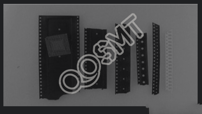
4. Tubular feeder
Generally, PLCC and SOIC are supplied with tube feeders. Load the components into the tubes with the pins oriented in the same direction for each device. End plugs secure the product in the tube, helping to minimize component movement during transportation and use. This protects the mechanical integrity of the package and leads, ensuring that they are not compromised during product distribution during manufacturing operations. The common tube feeders are shown in the figure below. Vibrating feeders are generally used to ensure that the components in the tube continue to enter the pick-up position of the patch head.
Features of tubular feeder:
• Good protection for component pins;
• Poor standardization;
• Poor stability;
• Lower productivity.
5. Bulk box feeder
The bulk box feeder puts components freely into formed plastic boxes or bags, and uses a vibrating feeder or feeding tube to feed the components into the placement machine in sequence. This method is used for MELF and small-profile semiconductor components without Suitable for polar components. Bulk box feeders are also called vibrating feeders.
The bulk feeder has three components: material box, hopper (Hopper) and vibrating feeder, as shown in the figure below.
Box feeder features:
• A dedicated feeder is required;
• Low packaging costs;
• Only suitable for non-polar rectangular and cylindrical components.
6. Feeder system
In feeder systems, ensuring component integrity is a key factor in improving placement reliability and efficiency. If the components in the feeder are twisted, reversed, empty, and the feeding position is unequal, it will be difficult to pick up the material, or even if the material is picked up, it will be difficult to identify it. If components with the above defects are pasted onto the board, they will be repaired. Therefore, to ensure that the feeder is in good working condition, regular maintenance is essential.
(1) Installation of the feeder (the method for filling the tray feeder is the same)
During production you need to replace the feeder. Doing this while the machine is running is strictly prohibited and requires the following steps.
① Press the Cycle Stop switch and wait for the machine to stop;
② Unplug or install the feeder;
③ Release the Cycle Stop button;
④ Press the Start button to continue production.
(2) Common feeder failure manifestations and solutions Common feeder failure manifestations and solutions are shown in the table below.