SMT Fuji machine NXT circuit board (PCB) clamping sensor adjustment method
Jan 27, 2024
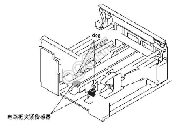
The light entrance and light avoidance of the circuit board clamping sensor can be adjusted by moving the position of the sensor dog.
1. Prepare items
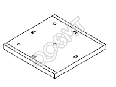
1. Adjust the fixture PM4577*
The adjustment jig is a 100mm square flat plate. The four side measurement parts are processed to a thickness of 7.5mm ± 0.01 and 7.4mm ± 0.01.
2. Adjustment method
1. Please pull the adjusted module forward. When adjusting the module with a side plate, remove the side plate to widen the space near the sensor.
2. Press the POWER button on the operation panel to put the module into sleep mode.
3. Change the width of the conveyor rail so that the adjustment jig can be installed. To change the width of the conveyor rail, please turn the round head screw.
(Remarks) There is also a method to easily change the track width. Before making adjustments here, please create a 100mm × 100mm circuit board job in advance. Please transfer this to the NXT machine and start production without the circuit board. The conveyor rail width is changed to 100mm.
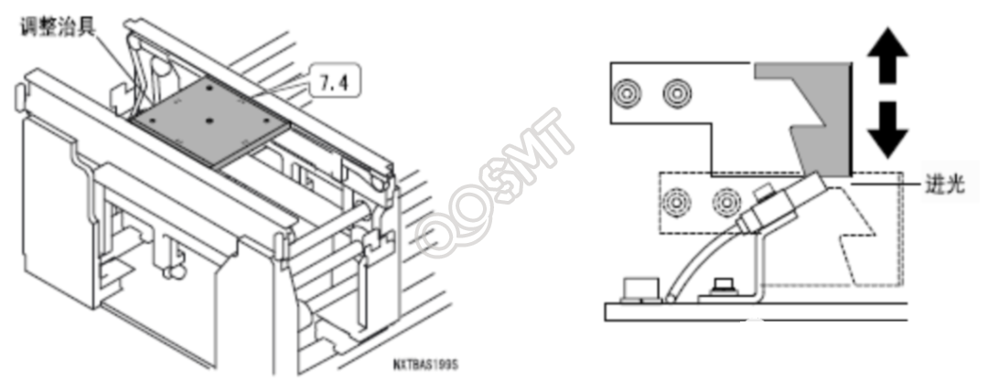
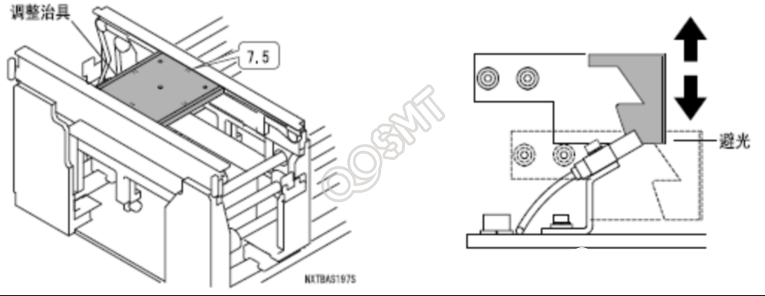
4. Install the "7.5mm" side of the adjustment jig to the rail of the conveyor rail
5. Please clamp the jig.
6. At this position, adjust the position of the dog while keeping the sensor out of the light.
7. Next, install the "7.4mm" side of the adjustment jig to the rail of the conveyor rail.
8. Please clamp the jig.
9. At this position, adjust the position of the dog so that the sensor is in the light state.
10. When using dual conveyor rails, please adjust the sensor on the 2nd side of the channel. The adjustment method is the same as the steps introduced here.
11. The above ends the adjustment operation. Please remove the adjustment jig from the conveyor rail.