In the field of electronics manufacturing, the precise operation of pick-and-place machines is crucial for product quality and production efficiency. This article will provide a detailed introduction to the operation procedures and measurement methods of the CM602 high-speed head, general-purpose head, and DT401-F pick-and-place machine, helping you to better master these devices and improve your production process.
I. Preparation:
1. For the CM402 high-speed head: 240×215 glass substrate, 1005 material, 110 nozzle, dedicated lamp and its power supply or dry batteries, double-sided tape.
2. For the CM402 general-purpose head: 240×215 glass substrate, test fixture (QFP as a material sample), 1003, 1004, and 1005 nozzles, dedicated lamp and its power supply or dry batteries, double-sided tape.
3. For the DT401-F: 240×215 glass substrate, test fixture (QFP as a material sample), tray fixture, tray, 3 each of 1003 and 1005 nozzles, dedicated lamp and its power supply or dry batteries, double-sided tape.
II. Preliminary Work (taking DT401 as an example):
1. Attach the glass substrate with double-sided tape;
2. Copy the appropriate program to the machine via floppy disk (usually 45 degrees) and return the machine to its home position;
3. Install the fixture on the fixture table and tray;
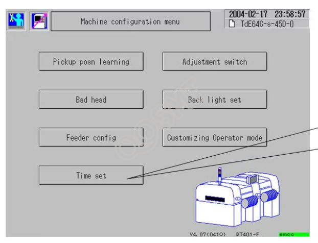
4. Modify the machine time (see next page);
5. Perform Z-axis origin correction;
III. Modifying Machine Time
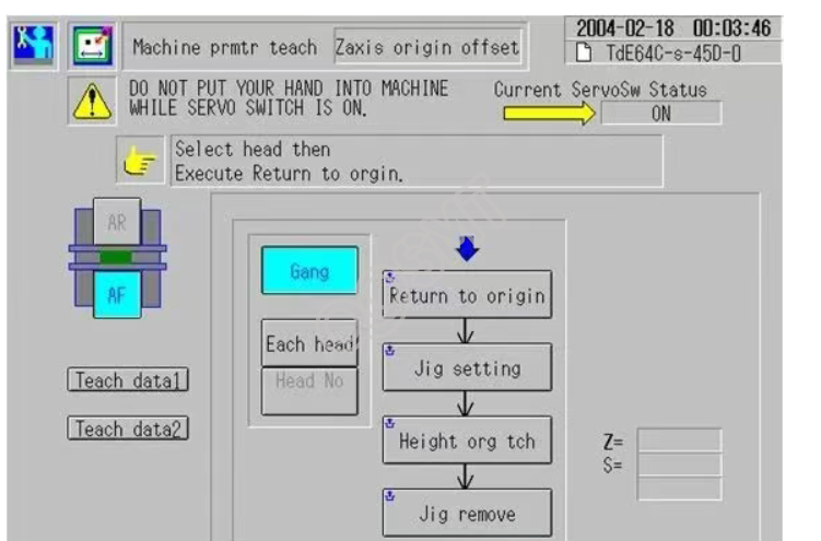
IV. Z-axis Origin Correction
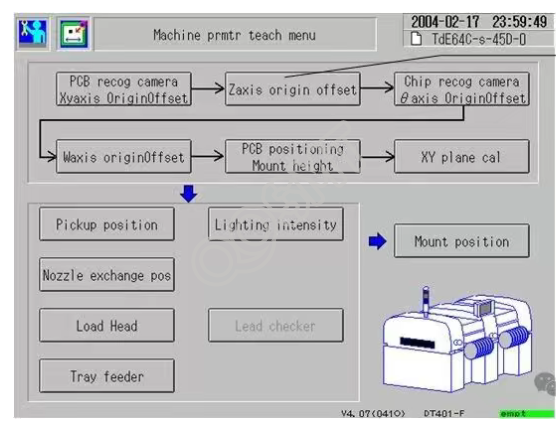
V. Detailed Operation Diagram for Z-axis Origin Correction
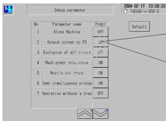
VI. Setting up Screen Printing to Floppy Disk
VII. Preparation for Measurement:
1. Place the glass fixture QFP on the bracket. Note that only stations 4-18 should be used, and the bracket should be aligned with the marked feeder number;
2. In tray No. 1, also install the glass fixture QFP, 3 in the X direction and 5 in the Y direction; A total of 30 glass fixture QFPs (which must be clean) are used. The orientation of the QFPs is such that the missing corner is in the upper left position when viewed from the loading position; 3. Place the lighting fixture in the appropriate position and turn it on. Note that improper placement may affect the fixture's recognition;
VIII. Measurement
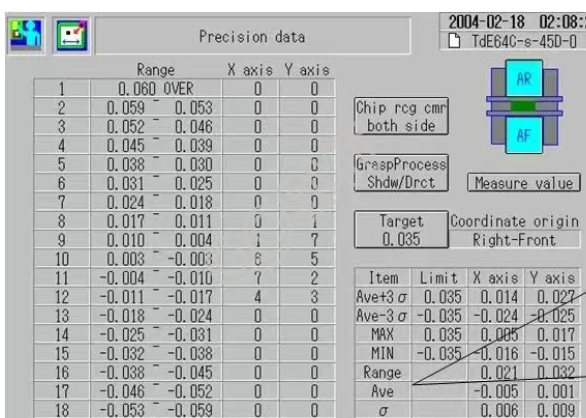
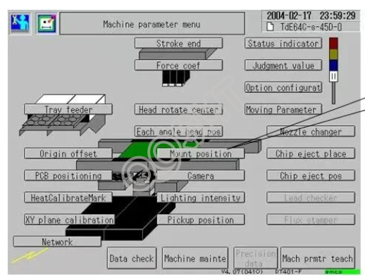
1. In the production screen, select placement position measurement. The machine will perform placement at a slower speed for measurement; 2. After the above is completed, perform accuracy measurement with the same preparation. At this time, the machine's placement speed will be faster. After completion, perform accuracy measurement. 3. After the above is completed, go to machine parameters as shown in the figure below. The indicator for the high-speed machine is 0.050, and the indicator for the general-purpose machine is 0.035. If it shows yellow, it means it is not acceptable and needs to be corrected.
IX. Precision data analysis
X. Correct mount
XI. Correct mount
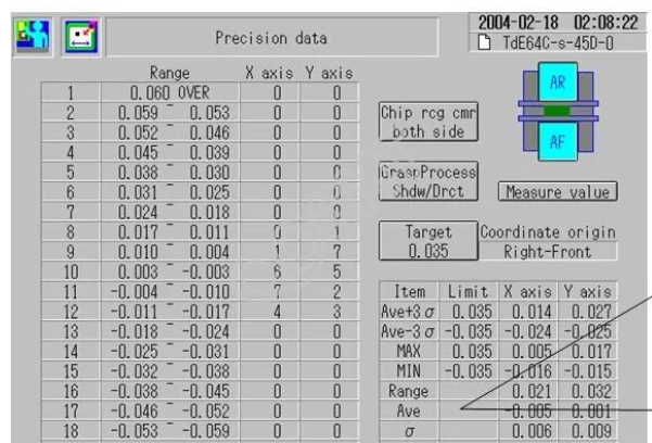
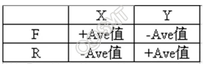
XII. Compensate the Ave value into the mount position
XIII.
Please remember to put away all the fixtures, tools, and equipment at the end, and include the images of the successfully completed target in your report.
Finally, we hope that through the detailed introduction in this article, you can master the operation and measurement methods of the CM402 high-speed head, general-purpose head, and DT401-F placement machine. In actual operation, please strictly follow the process and pay attention to safety regulations to ensure smooth production and high-quality products. We wish you a successful work!